Project: BLE Earrings
This is a set of earrings that flash when a message is sent from a phone/computer. All progress can be tracked on the BLEarrings Organisation.
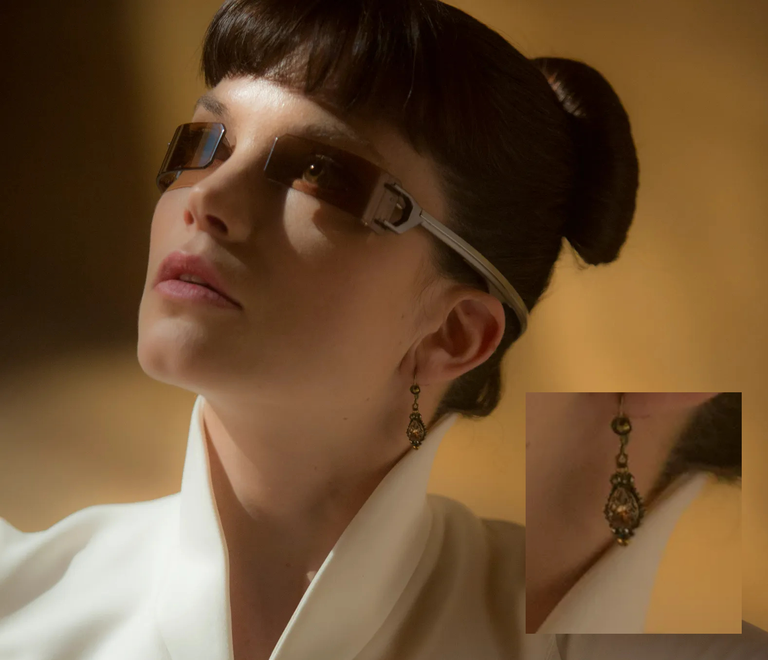
When I watched Bladerunner 2049 I saw Sylvia Hoeks playing Luv and in particular I saw her serving looks in this cool earring set. Whenever Jared Leto wanted to get her attention he blinked her earrings and she knew she had to go and do something dastardly. This spoke to me as someone who often struggles to drink water... what if I managed to make myself a futuristic bad bitch set of earrings that would remind me to carry out basic tasks? It can be done. The future is now.

Design Requirements
The key considerations for this project are: that it must be small and pretty as in the BladeRunner film, have a BOM I can afford (under £60 for prototype), be manufacturable on the 10cm x 10cm hotplate I have at home (no BGAs) and have a battery life that lasts at least one full day at work or with preference a full week. These requirements guided all primary design decisions.
Hardware
Elements
Earrings
One for the right ear and a mirrored layout for the left ear (the mirror is necessary because you cant buy a mirrored version of chips)- something obvious to others but not to me. Includes a battery and charge protections circuits, bluetooth antenna and connections to the neo-pixel pendant.
Dock
This is extra battery, a boost converter (to get from a 3V7 battery to 5V for USB) a hub to allow for USB communication with both earrings at once and serial broken out for flashing and debugging.
Pendant
This is the charm that hangs down from the earring. Basically just some connection points and a neo-pixel.
Which Micro?
The ESP32 (C3) and NRF52(833) were the two choices I picked between. Both are low cost, both have BLE, both have good BLE example documentation and layout examples and both had QFN package options. However, the ESP32 C3 had a much higher power consumption of 250mA when transmitting with BLE (due to its large functionality- dual bluetooth AND WiFi) than the NRF52833 which is 15mA and is targeted specifically at BLE applications. NRF52 boards also only consume 2.6uA with bluetooth off which is perfect for the earrings that wont transmit/ receive very often. I require the earrings to be as small as possible and therefore have the smallest battery, so need the lowest power consumption.
First Layouts and Panel
For the dock I followed the recommended layout (provided by the manufacturer) for the USB2422T-I/MJ chip I was using for the hub. This was used with the SIP32509DT-T1-GE3 power switch for the VBUS management. I used the recommendations provided in the BQ24073RGTR battery management IC for the battery management. Additionally I included a boost power supply to shift the 3.7V from the battery to the 5V needed to charge the earrings, the components for which I sized using the calculations on the chip datasheet.
For the earrings I followed the NRF52833 layout recommendations for bluetooth applications. I also used the LiPo Amigo Pro for the battery management on the earrings. I used the TI 2.4GHz pre-made antenna and followed their layout recommendations (no components placed too close to the antenna, matched impedance tracks to the antenna, nice uninterrupted ground plane next to the antenna) and matched impedance tracks for the USB connections. The size of the earring was limited by the size of the battery.
An annoying thing about making the two earrings is that they need to be mirrored to wear on each ear BUT they don't make mirrored micro packages (I didnt want the drone battery pressed against my head). For this reason a separate layout is needed for the left and right earring. I kept USB-C connector and the pendant connector in the same position but the entire layout is different otherwise.
The pendant is very simple but has no official terminal connection (only holes) to minimise size.
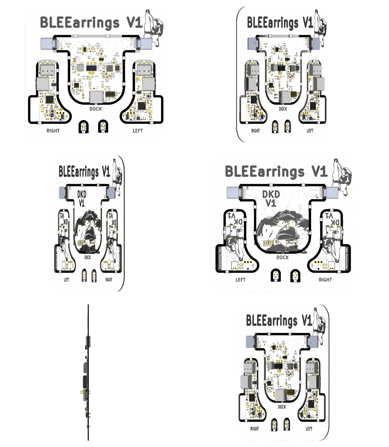
I combined the all elements on to one 10cmx10cm PCB and added some awesome silkscreen of orangutans from this stylish brummy monkey and this cool mother and baby monkey. Although I don't support keeping monkeys in captivity I do think they are SO cute! As all people know black and white is the most coquettish and y2k of all the soldermask-silkscreen combos so I got the boards in this.
Here's a cute gif of the PCB and a copy of the schematic. Again all resources for making your own version are at

We reflowed the PCB on the hotplate at home and I thought I would show a fun video of the moment the solder melted, recorded on the microscope camera. Populating this board was a nightmare, all 0402s and about 50 different packages. Some further BOM consolidation is needed- something I didnt pay much thought to for V1.
Software and Firmware
The firmware for the NRF52 needs to receive a colour command over bluetooth telling it to flash a certain colour. I have started writing this using the NRF52840-Dongle (No debugger) by creating the HEX using the Nordic nRF SDK plugin for VS Code and programming it with nRF Connect for Desktop. I use the Nordic nRF Connect app to send custom signals.
As for the software, Dom and Nat are thinking of making a cool mobile app to send the colors to the earring. This process hasn't started yet.